TurntablePSU.comReviews and Technical Analysis
Motors
AC Synchronous
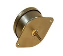
As the name implies, AC synchronous motors are driven by Alternating Current and the speed of rotation is synchronized or locked to the frequency of the driving signal. The speed of rotation is unaffected by voltage or torque load applied to the motor, until a point is reached where the motor stalls, known as cogging torque. The motor speed will either be 100% of rated speed or zero which makes speed regulation much easier to achieve.
AC synchronous motors use a permanent magnet rotor and the AC drive signal is applied to fixed windings called stators. The magnetic field created by the AC currents in the stator windings "rotates" with the drive frequency. The permanent magnet rotor will align itself with the magnetic field in the stators and thus will rotate at the same speed as the rotating magnetic field. The magnetic rotor and the fixed stator windings will have a number of poles that determine the speed of rotation. The poles are always set up in pairs and the speed of the motor (in RPM) will be Frequency x 60/Pole Pairs. Thus for a 60Hz motor with 12 poles, the speed will be 600 RPM (60 x 60/6). The same motor driven by 50Hz will be 500 RPM.
AC synchronous motors are constructed with 2 sets of windings and are mechanically rotated 90 degrees from each other. The windings need to be driven with AC currents that are also rotated 90 degrees apart and is usually accomplished by driving one winding directly with the other winding connected through a phase capacitor that creates the (near) 90 degree shift.
50Hz/60Hz: On almost all AC synch motors manufactured, there is no difference in the motor between 50Hz and 60Hz operation. Because of the difference in driving frequency, a different phase capacitor will be needed and the motor will turn at different speeds (500 vs 600 RPM, 250 vs 300 RPM), so the pulley required will be different between 50Hz and 60Hz operation to turn the platter at the correct speed.
300/600 RPM: The primary difference between a 300 RPM motor and 600 RPM motor (or 250 vs 500 RPM) is the 300 RPM motor has twice as many poles, thus half the speed (from the formula above). This has two effects on motor operation: 1. Cogging will be twice as fine (although still present) and 2. The 300 RPM motor will have twice the torque of a 600 RPM motor of the same power rating (Watts). Regarding the increase in torque, it does not equate to more powered delivered to the platter since the 300 RPM motor requires a pulley twice the diameter of the 600 RPM motor, therefore it has one half the mechanical advantage and the useable power delivered to the platter will be the same for both a 300 and 600 RPM motor of the same power rating. The other disadvantage of the 300 RPM motor is the belt burnout (the chirp heard when the motor starts) will be approximately twice as long as the motor speeds up almost instantaneously at power up, but the inertia of the platter will more difficult to overcome and the speed difference between platter and pulley will be worse for longer than when using a 600 RPM motor.
The relevant specifications for AC synch motors are: Power consumption (expressing in Watts or VA), Voltage, Speed (RPM), Poles and Torque output (expressed in Newton-Meters or NM).
AC Induction
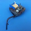
AC induction motors are similar in construction to AC synch motors, but instead of a permanent magnet rotor, the AC field of the stators induces a magnetic field in the rotor, thus creating an electromagnetic rotor. The magnetic field in the stator windings "rotates" at the drive frequency; if the rotor moved at the same speed as the rotating stator fields, the magnetic field would be the same at all times and thus incapable of inducing a signal in the rotor windings. If the rotor moves at a slower speed, the magnetic field will vary creating an induced AC current in the rotor which will create an electromagnet in the rotor. Because of this mechanism, the speed of an AC induction motor is semi-synchronous, being related to the driving frequency, but always slightly slower. The speed of an AC induction motor is affected by frequency, voltage and torque load, so speed regulation is more difficult.
The speed of an AC induction motor is similar to that of AC synch motors. The rotating speed (RPM) of the stator field is Frequency x 60/Pole Pairs. AC induction motors usually have 4 poles so the rotational speed of the stator field is 1800 RPM at 60Hz (60 x 60/2). As stated above, the rotor speed always lags the speed of the stator field so the operating speed of the motor will be typically 1700 RPM to 1750 RPM depending on motor construction, voltage and torque load applied.
AC induction motors are less efficient than AC synchronous motors, producing less torque output for a given amount of AC power input. The relavant specifications for AC induction motors are: Power consumption (expressing in Watts or VA), Voltage, Speed (RPM), Poles and Torque output (expressed in Newton-Meters or NM).
DC Motors
DC motors are nearly opposite in construction of AC synchronous motors in that they have a fixed permanent magnet stator and a rotor with windings to create an electromagnet. Since the rotor windings are fed with Direct Current instead of Alternating Current, the current needs to be commutated or changed as the windings rotate. This is done through the use of a commutating contacts and brushes that allows the DC current to be applied alternately to the windings in the rotor. The electromagnet created in the rotor windings will be attracted to the permanent magnet and cause to windings to rotate towards the permanent magnet. As the electromagnetic rotor passes the permanent magent pole, the current in the windings is switched to change the polarity of the electromagnet causing it to be attracted to then next permanent magnet pole and repelled by the pole just passed.
The speed of an DC motor is determined by the strength of the permanent magnet stators, the number of magnetic poles, the strength of DC current flowing through the windings in the rotor and the torque load. DC motors have a negative speed/torque slope; the more torque load that is applied, the slower the motor rotates and is the biggest obstacle to speed regulation. Even if the voltage driving the motor is well regulated, the speed will be very sensitive to changing loads.
The relevant specifications for DC motors are: Power consumption (expressing in Watts or VA), Voltage, No load and full load Speed, Speed constant (RPM/volt), Torque output (expressed in Newton-Meters or NM) and torque constant (RPM/NM).
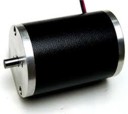
Brushless DC Motors
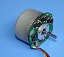
Brushless DC motors (BLDC) also known as Electrically Comutated (EC) motors, are a special class of DC motors that are constructed very similar to AC Synchronous motors, but with 3 phase windings (rotated 120 degrees apart) instead of 2. The rotor contains a permanent magnet and the windings are normally fed DC current, the flow and polarity of which can be switched electronically. The motor normally has 3 Hall Effect sensors spaced 120 degrees apart that signal the control electronics when to comutate or switch the current driving the windings. Configured this way, the speed control behaves similar to a DC motor in that the level of the drive currents control the speed and the sensors control how fast the currents are switched.
BLDC motors can also be driven by a 3 phase sinewave source and when done so, behave more like AC synchronous motors where the speed is determined by the driving frequency rather than the drive level, however for smoothest operation, the drive level should match the amplitude needed to run at the selected speed and will vary depending upon load. Driving BLDC motors in this fashion is fairly complex and requires the use of sophisticated electronics.
Most modern BLDC motors are designed for high power industrial applications and use ball bearings to allow larger radial loads which make them unsuitable for turntable use. Most of the Direct Drive turntables of the 70's and 80's used a lower power type of BLDC motor.
The relevant specifications for BLDC motors are: Power consumption (expressing in Watts or VA), Voltage, No load and full load Speed, Speed constant (RPM/volt) and Torque output (expressed in Newton-Meters or NM).
Cogging

Cogging can occur in all motors that use permanent magnets (whether on the rotor or stator) and iron cores used to house the windings. Cogging is caused by the attraction between the magnets and the iron core as the motor spins. The core has gaps between the poles of the stator where the attraction is minimal and solid portions where the attraction is maximum. In AC synch and BLDC motors, as the rotor moves between areas of minimum and maximum attraction, the motor "cogs" instead of spinning smoothly. On DC motors, the same phenomenon happens as the iron core rotor moves past the permanent magnet stators
Noise

As motors are mechanical devices, they all produce a certain amount of noise in operation. Common to all motors, is bearing noise, especially if the motor uses ball bearings. Friction bearings (sintered bronze, brass, Teflon, etc.) are quieter, but can still produce a hissing noise as the motor rotates, wear more than ball bearings and cannot support the larger radial loads that ball bearings can.
All motors that use iron cores and permanent magnets can produce vibration from the cogging that occurs as described above. All motors that are driven by AC currents can also vibrate at the line frequency if any of the components are loose (windings, laminations, bearings etc.).
DC motors have brushes that make contact with the comutation contacts on the rotor and can create mechanical noise as well as electrical noise (arcing).
Control Schemes
DC Motors
From the description above regarding DC motors, it would seem very easy to control the speed by merely controlling the voltage, therefore the current through the windings. The problem arises that all (brushed) DC motors have a winding resistance and a positive torque constant (amps/N-m). Because of the torque constant, when a load is placed on the motor, the current through the windings increases and causes more power to be disipated in the windings and less power available for the magnetic field to maintain the speed and the motor slows. To properly maintain accurate speed over all load conditions, the supply needs to sense the current draw of the motor and compensate its output voltage by the same amount to offset the loss of power in the windings. This type of feedback is in effect, negative resistance and constant speed will be achieved when the negative resistance of the supply equals the winding resistance of the motor. If the negative resistance of the supply is less than the winding resistance, the motor will still slow under load, but be better than no compensation. If the negative resistance of the supply is more than the winding resistance, the speed control may become unstable, increasing as more load is applied. To further complicate matters, the winding resistance of the motor can vary as the copper windings warm up with use.
AC Motors
AC synchronous motors are controlled by the frequency of the drive signal as are BLDC motors when properly driven by a 3 phase sinewave source. AC induction motors are semi-synchronous, therefore can be controlled somewhat by frequency alone, and more accurately with frequency and voltage used with a source of feedback. The drive frequency needed for 33 RPM is either 50 or 60Hz (depending on the pully installed on your turntable) and 67.5 or 81Hz for 45 RPM. The method of frequency control is the subject at hand.
 Analog Sinewave Generation
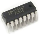
There are quite a number of analog circuits that can be used to generate accurate sinewaves, but the most widely used method is that of a dedicated integrated circuit (IC) function generator such as the Exar XR-2206. The IC requires very few external components to provide a reasonably stable sinewave with moderately low distortion (~1-2%) and adjustable amplitude. Frequency can drift somewhat with IC temperature and the part is discontinued by the only company that manufactured it.
 Crystal Oscillator and Digital Divider
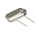
Crystal oscillators provide one of the most stable frequency sources available, but they are high frequency usually operating in the MHz range. Digital divider circuits can be used to reduce the output frequency to 50 or 60Hz, but the output of the digital circuits are square waves that need to be heavily filtered to produce clean sinewaves.
Crystal oscillators are also very limited in their adjustment range, moving only a few kHz at their operating frequency which translates to a small fraction of a Hz when divided down. Usually, one crystal is used for 33 RPM and another (higher frequency) for 45 RPM, but adjustment at each speed is not possible. Crystal frequencies that divide cleanly down to 50 or 60Hz are readily available, but ones that divide to 67.5 or 81Hz are not. Unless a custom crystal frequency is used, the accuracy at 45 RPM will be somewhat limited.
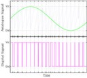 Pulse Width Modulation (PWM)
Pulse Width Modulation is a method of digital to analog conversion that uses fixed frequency square waves with variable duty cycle, when filtered, will produce an analog signal. In order to produce accurate and low distortion sinewaves, the duty cycle must be controlled in fine steps and changed many times more often than the final signal that is produced. If an accurate 60Hz sinewave is to be produced, the "sample rate" needed to change the duty cycle could be more than a hundred times higher or 6000Hz. PWM is complex to generate and usually requires a microprocessor to control the timing and frequency generation. The timing is therefore crystal controlled and stable, but because of the high update rate, will have somewhat limited resolution: To change between 60Hz and 60.01 Hz requires a timing change of 2.7uSec, but a change between 6000Hz and 6001Hz (the change in sampling rate) is 27nSec and difficult to do with any precision in the microprocessor as it will be limited by the crystal clock source.
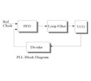 Phase Locked Loop (PLL)
Phase locked Loops use a control loop to alter the frequency of an analog oscillator and synthesize a wide range of signals in discrete step sizes. A voltage controlled oscillator (VCO) is the heart of a PLL circuit and is an oscillator whose frequency varies with the control voltage applied to its input. The output of the VCO is divided down digitally and compared to a fixed reference frequency that is usually dervived from a crystal oscillator and a digital divider. When the loop is "locked", the two frequencies will be the same; if the output of the VCO drifts off frequency, the 2 divided down signals will be different and an error voltage will be produced that is used to correct the VCO frequency. The output frequency is controlled by the frequency of the crystal controlled reference and the division ratio of the programmable divider connected to the VCO output: Fout= Ref Freq x Divisor. The digital divider circuit can only divide by integer values, so for each change of the divisor, the output frequency changes by Ref Freq which also controls the resolution of output signal.
Two problems arise when using PLL circuits: The output signal is derived from the VCO rather than directly from a crystal, so the stability will not be the same as a crystal controlled source. The other is that the PLL control scheme is a feedback circuit, and the error in output frequency is always corrected after it happens. The error detector is digital and its output is a varible duty cycle square wave that has to be low pass filtered (LPF) to produce a DC control voltage for the VCO. All LPFs have a delay between when the input changes and the result appears on the output. The lower the input frequency (Ref Freq in this case) the slower the response and the longer it takes to correct the frequency error. A Ref Freq of 0.1Hz (and therefore a synthesizer with frequency resolution of 0.1Hz steps) will be very slow to respond (hundreds of milliseconds). PLL circuits are best suited for RF applications were frequency steps are large and the loop bandwidth is high (settling time is short).
 Direct Digital Synthesis (DDS)
Direct Digital Synthesis is a digital frequency generator that uses a crystal controlled master clock to increase the count in an accumulator register by a fixed amount on each clock transistion. The register "accumulates" the count on each clock which increases linearly, until the maximum count is exceeded, the counter overflows to zero and the processes begins again and continues indefinitely. The amount the accumulator changes on each clock input is determined by the frequency control register: The larger the number, the faster the count accumulates, the lower the number, the slower the output changes. The accumulator contains a binary number between 0 and 2^N where N= the width of the register in bits. DDS accumulators are usually 24, 28 or 32 bits wide. The smallest number it can increase by is 1, so the frequency output resolution becomes MClk/(2^N); the higher N is (or the lower the Master Clock frequency) the finer the resolution. The output frequency is Freq Count x (MClk/2^N). For example, if the crystal frequency (MClk) is 4.096 MHz and the accumulator is 24 bits, the frequency resolution is .244140625 Hz (~ a quarter of a Hz). For 60Hz the Freq Count=246 (60.0585 Hz). If the crystal reference is divided down to 32kHz (÷128), the frequency resolution is 0.001907 Hz and Freq Count for 60Hz becomes 31,457 (59.9995 Hz). The same MClk with a 32 bit accumulator has a frequency resolution of 0.00000745 Hz and Freq Count for 60Hz becomes 8,053,064 (60.0000024 Hz).
The highest order bits of the accumulator are used as an address in a look up table that converts the linear phase accumulation into a sinewave amplitude value. This value is then sent to a digital to analog convertor (DAC) which produces an analog sinewave output. The DAC resolution is typically between 8 and 14 bits.
Because DDS is a feed forward system, it doesn't require a feedback loop and frequency changes take place on the next MClk input, are phase coherent and settle to the new frequency in uSecs. The output frequency will have the same stability as the crystal reference clock and phase noise will be better than the crystal by a factor of MClk/N where N is the frequency count. DDS is a type of sampling convertor, so the maximum frequency output is MClk/2 (Nyquist limit), but in practice, the output is usable to ~MClk/10. The closer the output frequency is to this limit, the worse the noise and spurious performance will be. Analog filters at the output of the DAC can reduce the noise and spurious content to low levels.
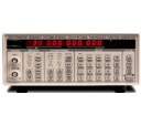
DDS is usually done by dedicated ICs that are complex to program and configure. A microprocessor is needed to compute the frequency count and perform the programming and communications with the DDS chip. DDS is commonly used in bench top test equipment and high end signal generators.
Clock Sources
 Analog
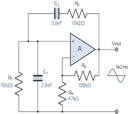
The Wien Bridge oscillator is probably the lowest distortion source available for low frequency sinewaves. With careful circuit design, frequency stability and accuracy will be moderate but all analog frequency sources will drift with temperature and voltage including IC function generators.
Crystal Oscillators
Uncompensated crystal oscillators provide a very accurate frequency source with reasonable stability over a wide range of temperature and voltage (~ 0.005-0.01% or 50-100PPM).
 Temperature Compensated Crystal Oscillators
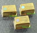
TCXOs have compensation circuits and use AT cut crystals for improved stability over a wider temperature range, typically achieving better than 0.00025% or 2.5PPM from -30°C to +60°C.
 Oven Controlled Crystal Oscillators
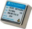
OCXOs are temperature compensated and maintain the temperature of the crystal in an "oven" that will always be higher than the ambient temp. OCXOs can achieve frequency stabilities of 0.000005% or 0.05 PPM.
Drive Components
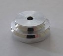 Pulleys
Belt drive turntables require a pulley on the motor shaft and a belt to transfer torque from the motor to the platter. The motor spins at a higher speed than the platter, so the pulley will be much smaller in diameter than the platter. The ratio of the pulley:platter diameter is also affected by the thickness of the belt so the formula becomes: (Motor Speed/Platter Speed)=(platter diameter + 1/2 belt thickness)/(pulley diameter + 1/2 belt thickness).
Pulleys that use flat belts are crowned (convex shaped) to keep the belt aligned, pulleys that use round belts are sometimes tapered for coarse speed adjustment and have grooves for the belt to ride in.
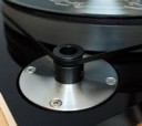
 Idler Wheels
An idler wheel can be used between the motor shaft and the platter, and the diameter of the idler wheel does not affect the platter speed. Most idler drive tables use higher speed motors (1800 RPM) and the idler drives the rim of the platter, either from the outside or underneath the platter, driving the inside of the rim. Lenco tables are unique in that the idler wheel is perpendicular to the underside of the platter and speed is changed by moving the idler wheel closer or further away from the spindle bearing at the center of the platter (the motor spindle is also tapered to reduce the amount of travel the idler must make to change speeds).
 Belts
Belts
Belts are used to transmit torque between the motor and the platter. They have the added benefit of isolating the motor vibrations from the rest of the table, especially if the motor is located outside of the plinth in a stand-alone assembly. Belts are usually made of rubber, but some tables use thread, mylar or kapton tape for belts. The problem with the more rigid materials is they transmit more noise to the table than elastic belts, and proper tension is much more difficult to achieve. Rubber belts are more forgiving than rigid belts, but belt creep is more pronounced.
Belt creep is different than belt slippage; slippage can be cured by proper tensioning, belt creep cannot be cured and is necessary to transmit torque. When the belt moves over the pulley to transmit power, the tension in the tight side is more than than the tension in slack side. As the belt material is elastic, it elongates more on the tight side than on slack side, resulting in unequal stretching on two sides of the drive.
Therefore, the length of the belt received by the driven pulley is more than the length that moves off the driven pulley. Hence, the belt must creep forward slightly relative to the driven pulley rim. On the other hand, the length of the belt received by the driving pulley is less than the length that moves off the driving pulley. Hence, the belt must creep back slightly relative to the driving pulley rim.
This motion of the belt relative to the driven and driving pulley due to unequal stretching of the two sides of the drive is known as belt creep. The effect of creep forward on the driven pulley is to slow down the speed of the driven pulley with respect to the belt and the effect of creep back on the driving pulley is to slow down the speed of belt with respect to the driving pulley. Thus the net effect of creep is to reduce the speed ratio lower than the theoretical expected speed.
Belt creep is due to the elastic property of the belt whereas the conventional slip is due to insufficient frictional grip between the belt and pulley. However, the effect of the creep as well as slip is to reduce the speed ratio, and hence power transmission. This is the biggest obstacle to speed control in belt drive turntables; no matter how accurate the speed of the motor is, the platter speed is determined by pulley diameter and tolerances, belt thickness, belt slippage and creep.