TurntablePSU.comReviews and Technical Analysis
VPI Analog Drive System
Overview
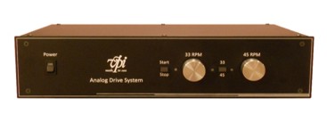
The $1250 VPI Analog Drive System (ADS) is a Variable Frequency Drive (VFD) that uses two separate analog circuits to generate the 33/45 RPM sinewave signal. The ADS is the replacement for the SDS power supply, with no digital circuitry and fewer features than the SDS. Frequency adjustment for each speed is done via front panel potentiometers (one for each speed) with center detent at the 12 o'clock position. Voltage reduction is automatically done after 8 seconds and the level is fixed at 92VAC. The front panel has an On/Off rocker switch that powers the unit down, a push button switch to change between 33 and 45 RPM and a motor on/off switch used when the user wishes to stop the platter.
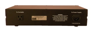
The ADS is powered by a 120/220VAC (factory selectable) direct input and the PSU has one output for the motor, rated at 20W maximum. The device we reviewed was factory configured for 60Hz and 115VAC output. There is a separate version of the ADS that is factory configured for 50Hz 230VAC output. The two are not field upgradeable.
The turntable can be used at 78 RPM if the motor is fitted with the optional pulley. The ADS is set to 33 RPM (60 Hz) for 78 RPM and the pulley is moved to the largest of the 3 spindles.
The ADS uses a stamped steel case that is similar in size to the SDS. The front panel is 0.125" thick aluminum. The case is black epoxy powder coating.
Circuit Description
The ADS uses two MC33072 opamp Wien-bridge oscillators with miniature lamps for stabilization, to generate the sinewave for 33 and 45 RPM. As with all analog oscillators, the ADS is not as stable as its crystal controlled predecessor. The power supply for the oscillators are connected to the same supply as the output amp (through 10 Ohms/4U7 decoupling) rather than a regulated DC voltage. The voltage drops from ±15.6VDC (no load) to ±12.5VDC (15W). The detent position for the frequency adjustments is fixed at the factory, but the center frequency will vary with time and temperature. The two analog pots allow for fine frequency adjustment, but the minimum adjustment on either side of the center position is ±0.30 Hz because of the detent. While center position of the control is factory set for 60Hz (33.33 RPM), the minimum adjustment starts at 59.68Hz (ccw) and 60.3Hz (cw) (33.155 and 33.500 RPM respectively). Full scale adjustment of the frequency is ±3Hz for both 33 and 45 RPM. The input and output transformers are split bobbin type IE construction. The sinewave signal is amplified by an all discrete device bipolar amp with a complimentary output stage in push pull. The output of the push pull amp is directly coupled to the low voltage windings of a 6.3VAC IE construction transformer. The output of the transformer is the HV windings and provides 115VAC to the output connector. The output impedance was 126 Ohms at 20W, slightly lower than the SDS (132 Ohms at 20W). In order to maintain voltage (115VAC) at full load, the output was set high (137VAC no load) and the waveform was clipped (4.7% distortion). At reduced voltage (99VAC no load, 90VAC 20W), the distortion was 0.6%. The clipping of the sinewave at start up increased the amount of mechanical buzz heard from the transformers which use laminate cores and are subject to hum at the line frequency. When the signal dropped to 92VAC, the hum was reduced, but still audible.
Measurements
The output frequency at 33.3 RPM measured 60.04 Hz and 80.97 Hz at 45 RPM at room temperature (72°F). Adjustment range of the speed was ±3.25 Hz for both 33 and 45 RPM modes. No load voltage at full/reduced output was 137/99 VAC; the output dropped to 134/97 VAC at 5W, 125/95.3 VAC at 10W and 115/90 VAC at 20W. With a 15W load (10.25W at 92 VAC reduced setting) the ADS got quite warm; the internal heat sink temp reached 145°F after 30 minutes and the internal air temp reached 96°F. Because the sinewave generator is analog based, the frequency drifted by +0.250 Hz after 1 hour of playing time (33.44 RPM) as seen Here. Short term stability of the oscillators were good when started at room temp, but as the ADS warmed up, the frequency stability wavered ±0.02 Hz (±0.011 RPM) which is similar to the short term variations of the average wall socket.
Specifications
Nominal Speeds...........................33 and 45 RPM (78 RPM Optional with modified pulley).
Distortion (Freq Generator).............0.025%
Distortion (115VAC output).............0.65%
Pitch Control................................±3.25 Hz
Output Power...............................200mA (20W)
Output Imdedance........................126 Ohms (20W)
Reduced Voltage..........................92VAC fixed
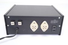
Turntable Connection....................NEMA 5-15 socket on back panel 115VAC
Input...........................................120VAC 1A input on IEC C13 socket
Dimensions.................................16"W x 12"D x 3"H
Weight........................................10 lbs.
Retail..........................................$1250
VPI HW40 Direct Drive
Overview
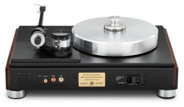
The $22,000 VPI HW40 Direct Drive uses a 500W ThinGap $600 TG231 coreless BLDC motor with the rotor directly mounted to a 6" subplatter. The 25lb main platter rides on top of the subplatter. The stator and the platter bearing (inverted type) are mounted to an aluminum hub that is bolted to the plinth top plate. The motor is driven by an industrial controller made by Elmo Motion Control (Gold Solo Twitter) in Israel. The motor, controller and associated electronics are mounted to the bottom of a 1/2" aluminum top plate that makes up an improved version of the VPI Classic chassis. There are 3 push button metal switches on the top of the plinth for 33, 45 and standby mode. The internal power supply can be wired for 115 or 230VAC input.
Circuit Description
The Elmo G-SOLTWI6/100 controller drives the motor as a DC type using block (trapezoidal) communtation and Hall sensors with PWM output to the motor at 10kHz and speed feedback from an MR100F085A160E00 magnetic ring encoder made by RLS company in Slovenia. The encoder ring is mounted to the bottom of the subplatter, and has 160 poles (80N & 80S) spaced 2mm apart which produce 80 pulses per revolution. The RLS RLMDICA03BB15C00 encoder reads the 80 PPR encoder ring and synthesizes 8 pulses out for every decoded pulse in, producing 640PPR. It also synthesizes a primary pulse train and a quadrature pulse train, effectvely doubling the PPR to 1280. The pulse train is level shifted from single ended TTL to RS485 by an RLS RLACC encoder module. The Elmo controller can create a count on both positive and negative edges of the dual pulse train, effectively doubling the resolution of the ring encoder to 2560 PPR. At 33.333 RPM (1.8S/rev), the count becomes 1422.222 counts per second which is rounded up to 1423 for a speed of 33.351 RPM. Reading either the A or B output of the encoder directly, produces a 355.75Hz square wave (1423 counts per sec/4) with a stability of +1.5Hz to -1.0Hz (+0.4% to -0.28%) worse case.
The controller is very compact measuring 1.89" x 1.18" x 0.98" with 5 stacked circuit boards very densely populated. The $570 Elmo controller does not appear to be field servicable. The controller interfaces to the rest of the hardware via two 30 pin connectors and one 6 pin connector to the motor. There is an 8 pin connector for communications with the PC.
The power supply for the motor/controller is a Toroid Corporation PN 707.222 22VAC at 2.5A (57W) transformer which produces the 36VDC unregulated supply rail. The logic and control supplies at 5VDC and 24VDC are provided by linear IC regulators.
Measurements
The Elmo controller provides closed loop feedback speed control with a simple PI control loop and a 20Hz digital LPF. This is very similar to the direct drive tables of the 70's and 80's but with a heavier platter and longer time constants. The time constant of the servo control measured ~500mS, taking 250mS to detect a speed change due to drag and another 250mS to correct the speed dip. The acceleration control is set to 900 counts per second maximum in software. Start up takes approximately 1.58 seconds (1423/900).
The accuracy of the ring encoder is spec'd at 0.035% W&F error with a 50 micron mounting eccentricity (due to machining error or changes in glue thickness). Comparing the 355Hz encoder output with a stable source showed much higher speed deviations of +1.5Hz/-1.0Hz (+.421%/-.281%). Elmo Motion Control provides software (called EASII, available Here; the software is free, but does require on-line registration to download) to adjust and monitor the motor/encoder/controller performance via a serial port (8 pin Communications connector) connected to a PC via a custom cable. Using the software, the count for each revolution can vary ±1 count or 0.07% W&F (1/1423), however the instantaneous speed error showed higher deviations. The measured platter speed varied from 33.328 (count=1422) to 33.351 (count=1423). In addition to monitoring the controller/motor, the software can start/stop the motor and can change platter speed by altering the count (count=RPM*2560/60). Using a test LP and measuring W&F with a Leader LFM-39A meter produced similar (0.07%) results.
The output of the Elmo controller is three PWM square waves of 36VPP at 10kHz. As the duty cycle of the three outputs vary, it creates a voltage difference between the windings that drive the motor, similar to a switched mode power supply. The output signal is current limited in software to 11.6A (40W into the 0.3R windings). At maximum power out, the motor produces 0.74 Nm of torque; during normal running time the torque drops to 0.0068Nm. There is little to no filtering between the controller and the motor, so the motor windings are driven by three 10kHz square waves; at start up, a high pitch whine can be heard coming from the motor. There is no magnetic shielding around the controller or motor and no filtering between the controller and motor.
Specifications
Nominal Speeds...........................33 and 45 RPM
Distortion ....................................N/A (DC control, block communation at 10kHz)
Pitch Control................................None
Output Power...............................40W maximum
Output voltage.............................375mV (33 RPM) 485mV (45 RPM)
Reduced Voltage..........................N/A
Output Torque..............................0.74 Nm max / 0.0068 Nm nominal
Turntable Connection....................IEC C14 socket on back panel
Input...........................................115/230VAC 1A input on IEC C14 socket
Dimensions.................................22"W x 17"D x 10"H
Weight........................................70 lbs.
Retail..........................................$22,000
VPI Power Line Conditioner (Early Version)
Overview
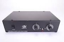
The VPI Power Line Conditioner (PLC) has two distinct models. The early version had continuously variable dials for each speed (33/45 RPM). The dials controlled a digital oscillator that produced the 60Hz or 81Hz square wave signal for the motor. The oscillator signal fed a 4049 inverter that created 2 out of phase square wave signals that drove a bipolar output amp connected to a step up transformer to create the high voltage supply for the motor. There is a front panel rocker switch to turn the unit on/off and a slide switch to select 33/45 RPM.
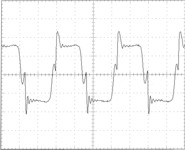
The design is similar to the early power inverters that boosted a car battery up to 120VAC to power drills, soldering irons etc. One of the problems with this type of circuit is the output is a modified square wave rather than a sine wave so the motor will run hotter and noisier; if measured with an RMS voltmeter the 120VAC output actually reads closer to 140VAC.
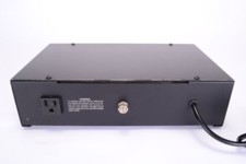
The PLC is powered by a 120VAC direct input and the PSU has one output for 120VAC motors. There is a rear adjustment for the output voltage on some of the newer units that allows for reduction of the output voltage by 40%; the control adjusts the output voltage for both speeds. The PLC does not work with 50Hz motors.
Circuit Description
The PLC uses a variable frequency oscillator to create the 60Hz/81Hz square wave signal. The signal is split into 2 phases by the 4049 inverter and drives the output transistors 2N3904/2N3055 in a quasi-darlington push-pull configuration. The output of the push pull amp is directly coupled to the low voltage windings of a 26VAC IE construction transformer. The output of the transformer is the HV windings and provides 120VAC to the output connector.
Measurements
The output frequency at 33.3 RPM (dial centered) measured 58.3 Hz and 83.6 Hz at 45 RPM (dial centered). Adjustment range of the speed was ~ +/- 5Hz for 33 RPM and +/- 7.5 Hz for 45 RPM. No load voltage at the 120VAC output was 143 VAC; the output dropped to 136 VAC at 5W, and 131 VAC at 10W. The output waveform is a ringing squarewave with severe distortion.
Specifications
Nominal Speeds...........................33 and 45 RPM
Speed Stability.............................N/A
Distortion (Freq Generator)............Not Applicable (Square Waves)
Distortion (115VAC output)............31%
Pitch Control................................+/- 5Hz (33 RPM) +/- 7.5 Hz (45 RPM)
Output Power...............................N/A
Output Imdedance........................143 Ohms (10W)
Reduced Voltage..........................Rear Panel 100-60% (140VAC to 84VAC)
Turntable Connection....................NEMA 1-15 socket on back panel 120VAC
Input...........................................120VAC 1A input
Dimensions.................................9"W x 6"D x 2"H
Weight........................................6.25 lbs.
Retail..........................................N/A
VPI Power Line Conditioner (Thumb Wheel Version)
Overview
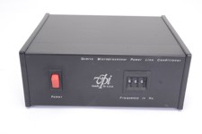
The later version of the VPI Power Line Conditioner (PLC) is a PLL based square generator; the synthesizer uses 3 thumb wheel switches to set the output frequency with 0.1 Hz resolution. The range of frequency adjustment is 50.0 Hz to 99.9 Hz in 0.1Hz steps. There is a front panel rocker switch to turn the unit on/off. There is no switch to select 33/45 RPM, the use must change to the correct frequency or move the belt. There is no adjustment for the output voltage.
The design is similar to the early power inverters that boosted a car battery up to 120VAC to power drills, soldering irons etc. One of the problems with this type of circuit is the output is a modified square wave rather than a sine wave so the motor will run hotter and noisier; if measured with an RMS voltmeter the 120VAC output actually reads closer to 140VAC.
The case of the PLC is a wrap around aluminum sheet with plastic sides. The PLC is powered by a 120VAC direct input and the PSU has one output for 120VAC motors. The PLC does not work with 50Hz motors.
Circuit Description
The PLC is a PLL based squarewave generator using an MC4046 PLL/VCO IC. Although the front panel says "Microprocessor", all of the circuitry is discrete digital logic. The reference crystal is 3.579545 MHz and divided down to the 100Hz reference by an MM5369 IC. The VCO output is 1000 times the output frequency (50kHz to 99.9kHz) and is divided down to 100Hz by a CD4059 programmable divider IC; the division ratio (500-999) is controlled by the 3 thumb wheel switches. The VCO output is also divided down by 100 via a 4518 dual decade counter; the output of the dual counter is further divided by 10 via a 7490 decade counter to create the output frequency 50Hz-99.9Hz. The signal is split into 2 phases by a 4049 inverter and drives the output transistors 2N3904/2N3055 in a quasi-darlington push-pull configuration. The output of the push pull amp is directly coupled to the low voltage windings of a 26VAC IE construction transformer. The output of the transformer is the HV windings and provides 120VAC to the output connector.
Measurements
The output frequency at 60.0 Hz measured 59.8 Hz and 80.7 Hz at 81.0Hz. No load voltage at the 120VAC output was 143 VAC; the output dropped to 136 VAC at 5W, and 131 VAC at 10W. The output waveform is a ringing squarewave with severe distortion.
Specifications
Nominal Speeds...........................33 and 45 RPM
Speed Stability.............................0.01% (100 PPM)
Distortion (Freq Generator).............Not Applicable (Square Wave)
Distortion (115VAC output).............31%
Pitch Control................................50.0Hz to 99.9Hz in 0.1Hz steps
Output Power...............................N/A
Output Imdedance........................143 Ohms (10W)
Reduced Voltage..........................Not Available
Turntable Connection....................NEMA 1-15 socket on back panel 120VAC
Input...........................................120VAC 1A input
Dimensions.................................8.25"W x 7"D x 3.5"H
Weight........................................6.25 lbs.
Retail..........................................N/A
VPI Synchronous Drive System
Overview
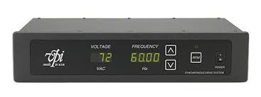
The $1400 VPI Synchronous Drive System (SDS) is a Variable Frequency Drive (VFD) that uses a PLL to generate the sinewave signal. The unit uses an Atmel AT89C51 microprocessor to control the PLL circuit, the display and accept commands from the user. The clock source for the microprocessor is a 7.32728MHz crystal oscillator with a frequency stability of .01% (100 PPM) and also serves as the reference source for the PLL. The display uses 7 large LEDs to indicate speed / output voltage and the front panel has 3 buttons to switch between 33/45 RPM and to control the output frequency for each speed in 0.01 Hz steps. The front panel has an On/Off rocker switch that powers the unit down when the user wishes to stop the platter.
The SDS is powered by a 120/220VAC direct input and the PSU has one output for 120VAC motors, rated at 20W maximum. The output voltage will revert to one of 8 lower levels between 115VAC and 72VAC in 6 volt steps after approximately 3 seconds. Unlike most of the other PSUs on the market, the display of the SDS shows the actual frequency rather than RPM and is adjustable in 0.01 Hz steps from 52 Hz to 91 Hz. The standard frequency step for 0.1 RPM is 0.18Hz and 0.1333 Hz (33/45 RPM). The SDS does not work with 50Hz motors. The input to the SDS can be 115 or 230VAC but the output is 115VAC only.
The turntable can be used at 78 RPM if the motor is fitted with the optional pulley. The SDS is set to 33 RPM (60 Hz) for 78 RPM and the pulley is moved to the largest of the 3 spindles. In 78 RPM mode, 0.1 RPM changes require 0.0769 Hz changes.
The SDS has a calbration mode that is entered by holding the Up and Down buttons while switching on the power. The user advances through the calibration modes (numbered C1-C6) by pressing the 33/45 RPM button. The six calibration modes are: C1: 90Hz output. C2: Number of power on cycles. C3A/B: Hours of run time. C4: Reduced voltage 33 RPM. C5: Reduced voltage 45 RPM. C6: Firmware Version.
The SDS uses a stamped steel case that is very sturdy. The front panel is 1/4" thick aluminnum with a sealed membrane keypad for user interface. The case is black epoxy powder coating.
Circuit Description
The SDS uses a conventional analog PLL circuit based on the Motorola MC4069 PLL chip with phase detector and VCO. Where it is unconventional is the entire frequency scheme is scaled by 65,536. Normally, with a frequency resolution of 0.01 Hz, the lock time would be extremely long and the loop bandwidth would be very low. The VCO operates at the output frequency x 65,536 and the frequency step is 655.36 Hz. The output of the VCO is divided by 4096 which then clocks a divide by 16 binary counter whose 4 outputs drive an analog mux configured as a 3 bit DAC. The stepped waveform of the DAC is lowpass filtered by a 2 pole Sallen-Key low pass filter with a cutoff frequency of 190 Hz then applied to another analog mux that selects one of 8 output levels. The final sinewave signal is amplified by an LM392 opamp that drives a complimentary bipolar/MOSFET output stage in push pull. The output of the push pull amp is AC coupled to the low voltage windings of a 6.3VAC IE construction transformer. The output of the transformer is the HV windings and provides 115VAC to the output connector.
Measurements
The output frequency at 33.3 RPM measured 60.00 Hz and 81.00 Hz at 45 RPM. Adjustment range of the speed was from 52 Hz to 91 Hz in 0.01 RPM steps for both 33 and 45 RPM modes. No load voltage at the 115VAC output was 113.6VAC; the output dropped to 108.9VAC at 5W, 103.5VAC at 10W and 94.7VAC at 20W. The unit also got quite hot at 20W with the heat sink temp topping out at over 140°F. Because the control circuit is PLL based, the output became somewhat unstable when changing between 33 and 45 RPM.
Specifications
Nominal Speeds...........................33 and 45 RPM (78 RPM Optional with modified pulley).
Speed Stability.............................0.01%
Distortion (Freq Generator).............0.185%
Distortion (115VAC output).............0.39%
Pitch Control................................52-91 Hz in 0.01 Hz steps
Output Power...............................175mA (20W)
Output Imdedance........................132 Ohms (20W)
Reduced Voltage..........................115VAC to 72VAC in 6 volt steps
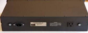
Turntable Connection....................NEMA 5-15 socket on back panel 115VAC
Input...........................................120VAC 1A input on IEC C13 socket
Dimensions.................................19"W x 9"D x 3.5"H
Weight........................................9.25 lbs.
Retail..........................................$1399